
Hey Ziglets, its ISE ISE Baby time!! Today we are continuing with our Cisco ISE 2.3 Blog Series by adding our NADs, or Network Access Devices, into our ISE Cluster. We are going to add our Lab Cisco 3750e switch into our ISE Cluster! This is our last blog post for 2017 so lets jump right into it!
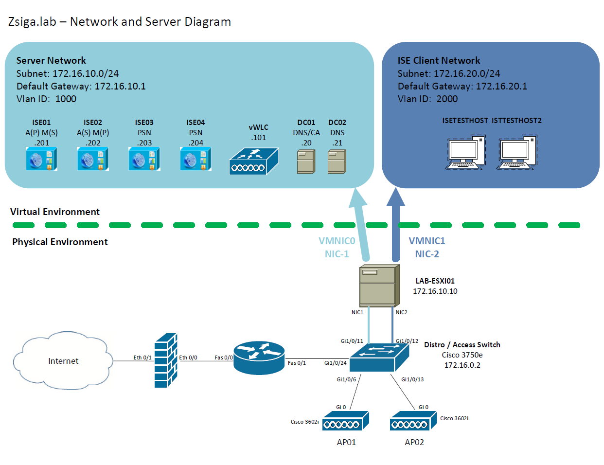
Network and Server Diagram:
Here is our reference diagram that we will be using throughout this blog series.
Related Posts:
If you haven’t seen these posts yet, you should check them out
- ZBISE01 – Basic Cisco ISE 2.3 VM Installation
- ZBISE02 – Building a Cisco ISE 2.3 Distributed Cluster
- ZBISE03 – Overview of our Cisco ISE 2.3 Use Cases for the ZBISE Blog Series
- ZBISE04 – Cisco ISE 2.3 Adding the ISE Cluster to Active Directory
- ZBISE05 – Virtual Wireless LAN Controller (vWLC) Install
The Steps!!
We are going to add our lab Cisco 3750e switch (172.16.0.2) as a Network Access Device, or NAD, into ISE. There are a number of configurations that will need to be added to both the 3750 and the ISE Cluster.
1. The Global Switch configuration for our Network Access Device:
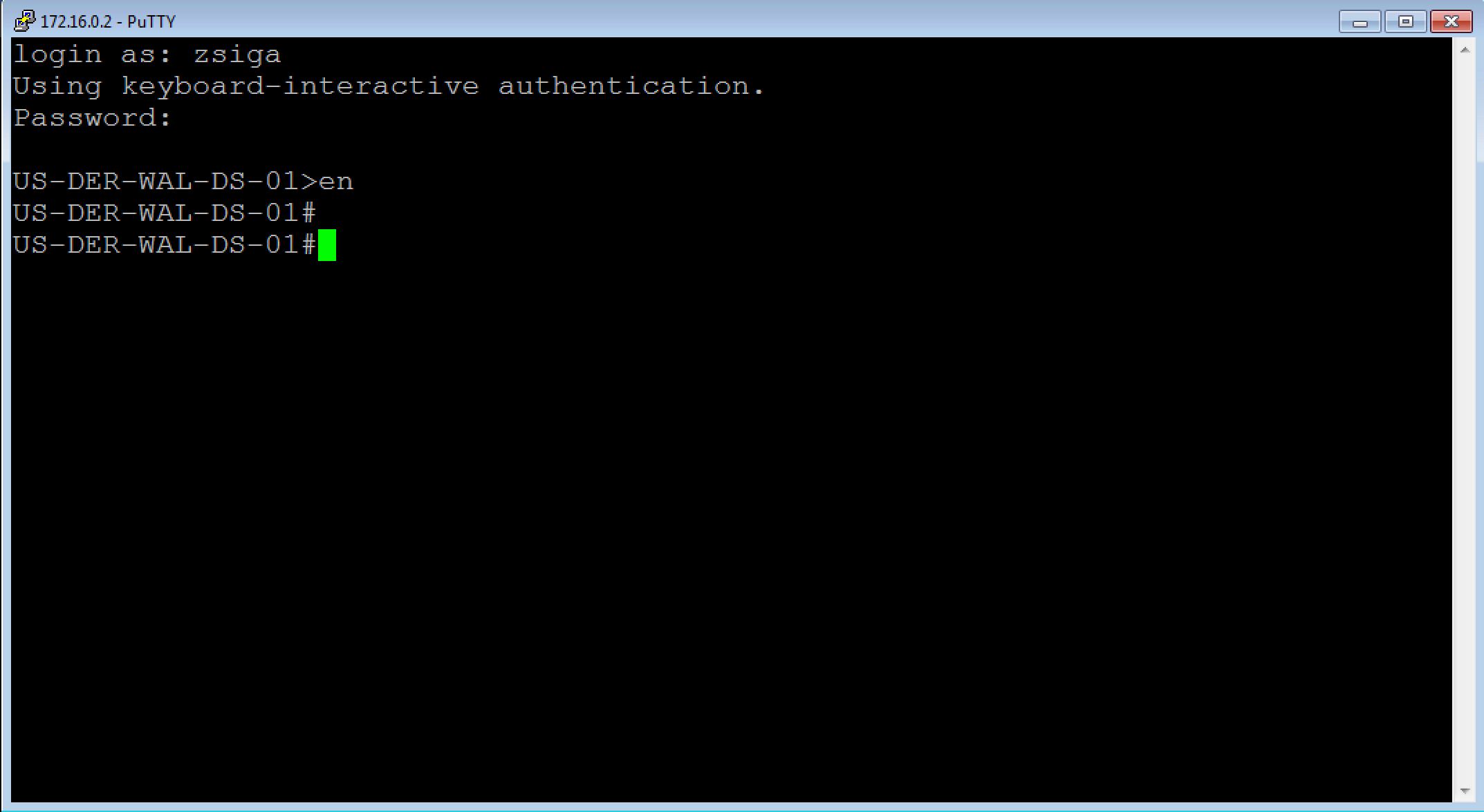
Launch your favorite SSH / Telnet client and log into your network switch, which is our Network Access Device for this installment. For our lab this is our Cisco 3750e and we will utilize the Loopback 0 address of 172.16.0.2 to ssh to it.
Now that we are logged into our switch, we are going to apply the following configurations.
NOTE: These configurations may not be the same on your IOS Version or Model of device. The commands may just not be available or they may have a different syntax altogether. Also, we are not enabling the Device sensor configurations because they are not supported on the IOS version we are running on this Cisco 3750e.
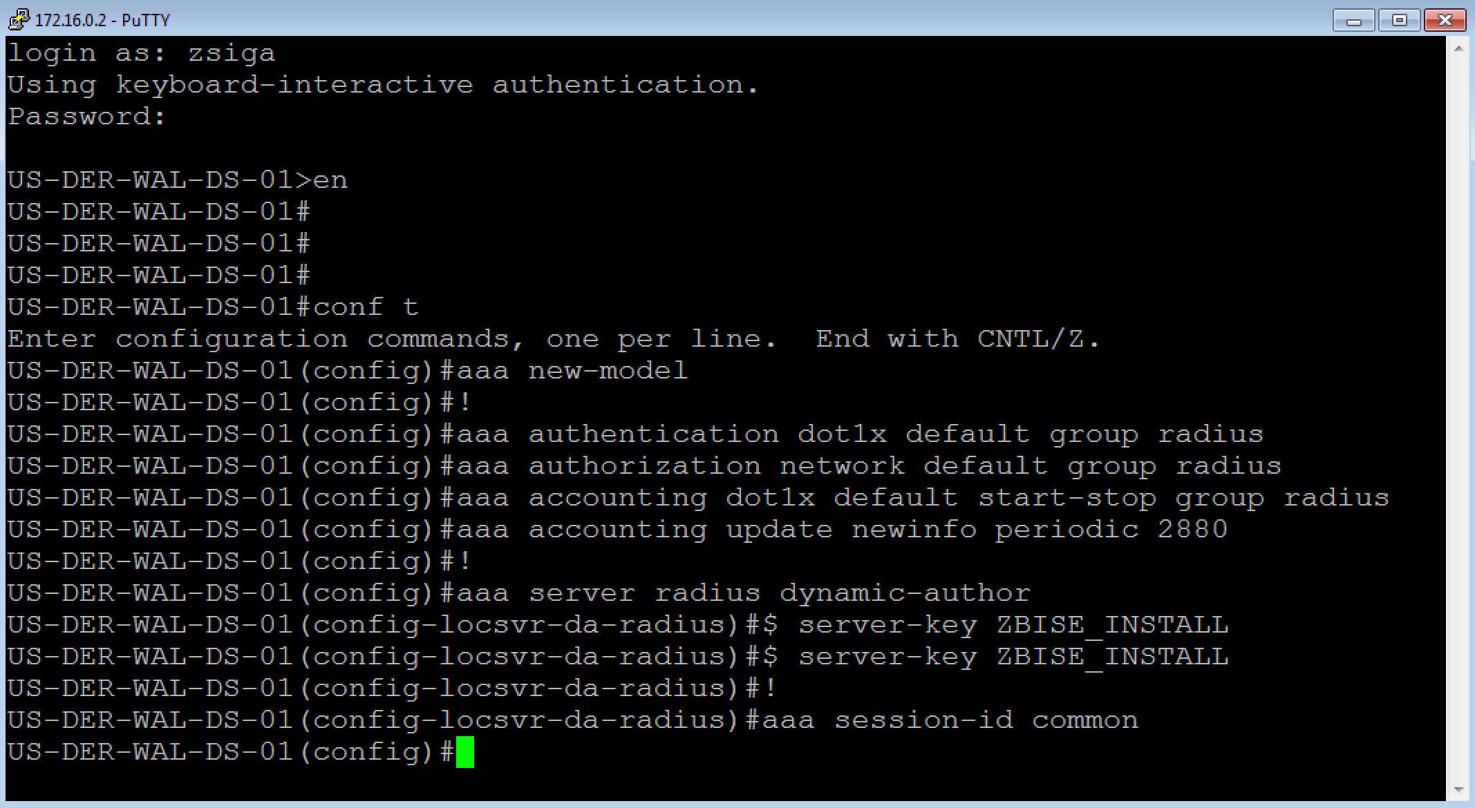
aaa new-model
!
aaa authentication dot1x default group radius
aaa authorization network default group radius
aaa accounting dot1x default start-stop group radius
aaa accounting update newinfo periodic 2880
!
aaa server radius dynamic-author
 client 172.16.10.203 server-key ZBISE_INSTALL
 client 172.16.10.204 server-key ZBISE_INSTALL
!
aaa session-id common
In this first section of configurations we enable Authentication, Authorization, and Accounting (AAA) and configure a number of settings to support it. The “aaa server radius dynamic-author” portion is specifically important here because it enables Change of Authorization (CoA) for this Network Access Device.
Below is a screenshot of what we did in our lab.
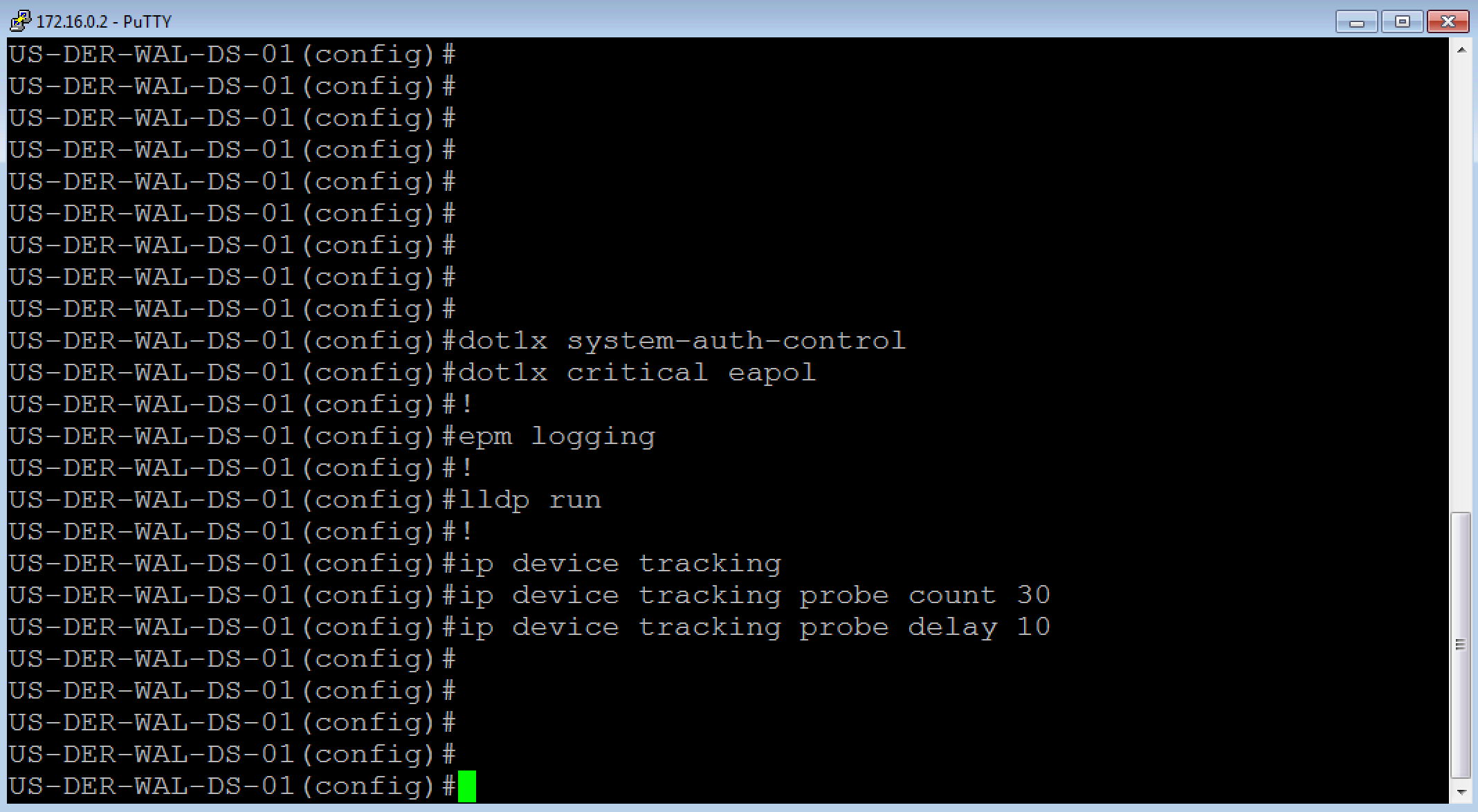
dot1x system-auth-control
dot1x critical eapol
!
epm logging
!
lldp run
!
ip device tracking
ip device tracking probe count 30
ip device tracking probe delay 10
In this section, we enable Dot1x, LLDP, and Device tracking on the switch. Dot1x is of course for authentication while Device Tracking is to find out the IP Addresses for the devices being connected to our NAD.
Here is what we did in the lab.
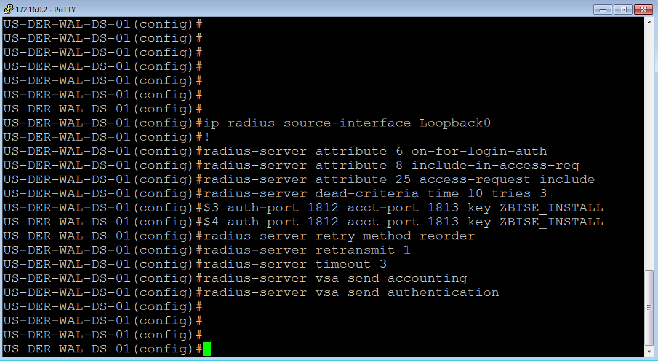
ip radius source-interface Loopback0
!
radius-server attribute 6 on-for-login-auth
radius-server attribute 8 include-in-access-req
radius-server attribute 25 access-request include
radius-server dead-criteria time 10 tries 3
radius-server host 172.16.10.203 auth-port 1812 acct-port 1813 key ZBISE_INSTALL
radius-server host 172.16.10.204 auth-port 1812 acct-port 1813 key ZBISE_INSTALL
radius-server retry method reorder
radius-server retransmit 1
radius-server timeout 3
radius-server vsa send accounting
radius-server vsa send authentication
This section is the Radius configuration section. For your radius servers, you should only need to add the PSNs in your deployment. You will see that I have ISE03 and ISE04 in this configuration only. You will also notice that I am sourcing all radius traffic from my loopback 0 address. I highly recommend doing this for all protocols as possible. If you do not have a loopback address then I would use a Layer 3 interface / SVI.
Here is our lab screenshot
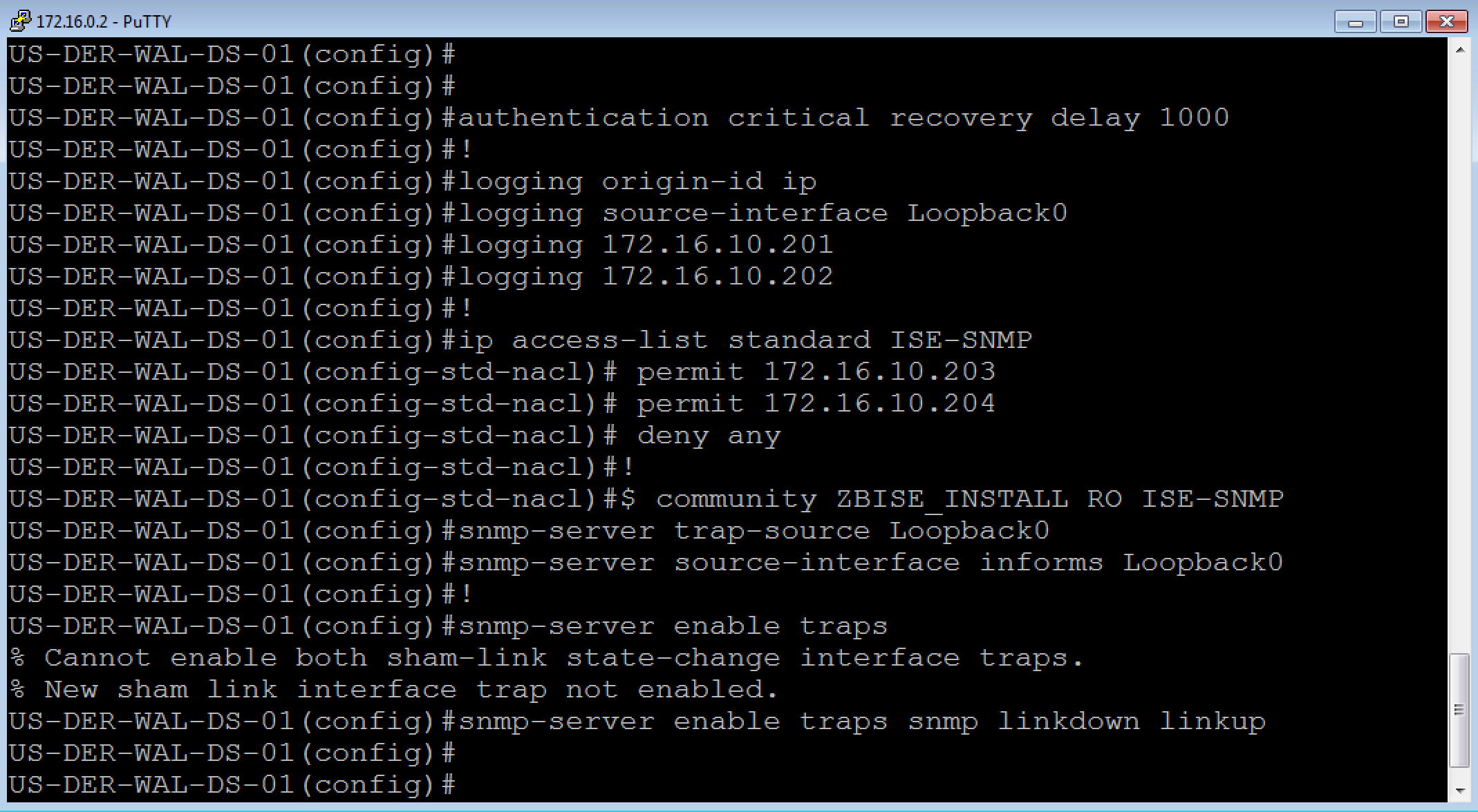
authentication critical recovery delay 1000
!
logging origin-id ip
logging source-interface Loopback0
logging 172.16.10.201
logging 172.16.10.202
!
ip access-list standard ISE-SNMP
 permit 172.16.10.203
 permit 172.16.10.204
 deny any
!
snmp-server community ZBISE_INSTALL RO ISE-SNMP
snmp-server trap-source Loopback0
snmp-server source-interface informs Loopback0
!
snmp-server enable traps
snmp-server enable traps snmp linkdown linkup
This is the Logging and SNMP section of the configuration, which for the most part should be self-explanatory. You will notice a standard ACL that is being used to restrict our SNMP community string. I personally like to do this so that I can limit what devices in my deployment can use a community string. In this case, the community string is read-only but you could make one that is read-write.
Here is our lab screenshot for these as well
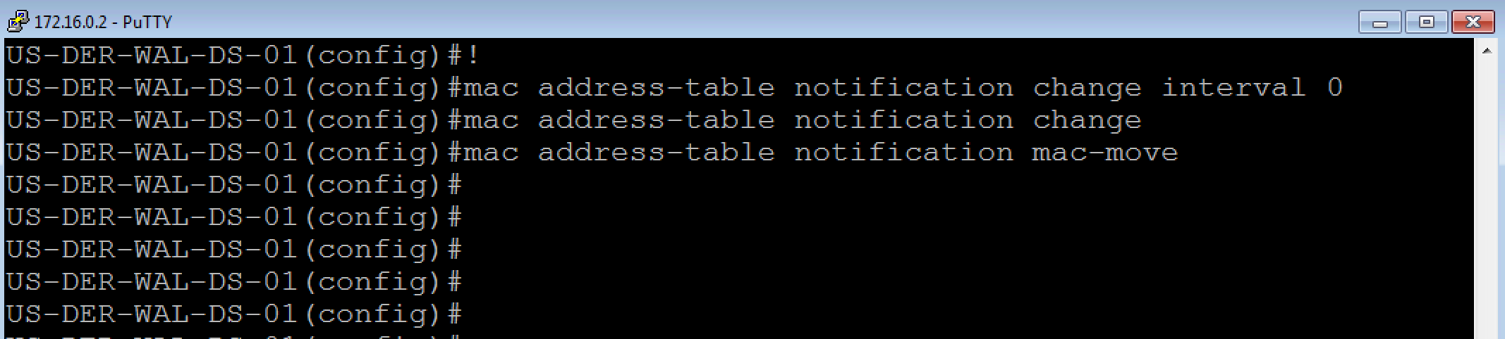
mac-notification change move threshold
!
mac address-table notification change interval 0
mac address-table notification change
mac address-table notification mac-move
This final section helps ISE receive mac address information to assist with profiling of devices.
2. The Switch Interface Configuration for our Network Access Device:
Now that we have the Global configurations completed on the Switch for our Network Access Device, we would normally configure a few test ports for ISE. Before configuring any port, I usually like to show the current configuration incase I need to revert the configuration in the future for any reason.
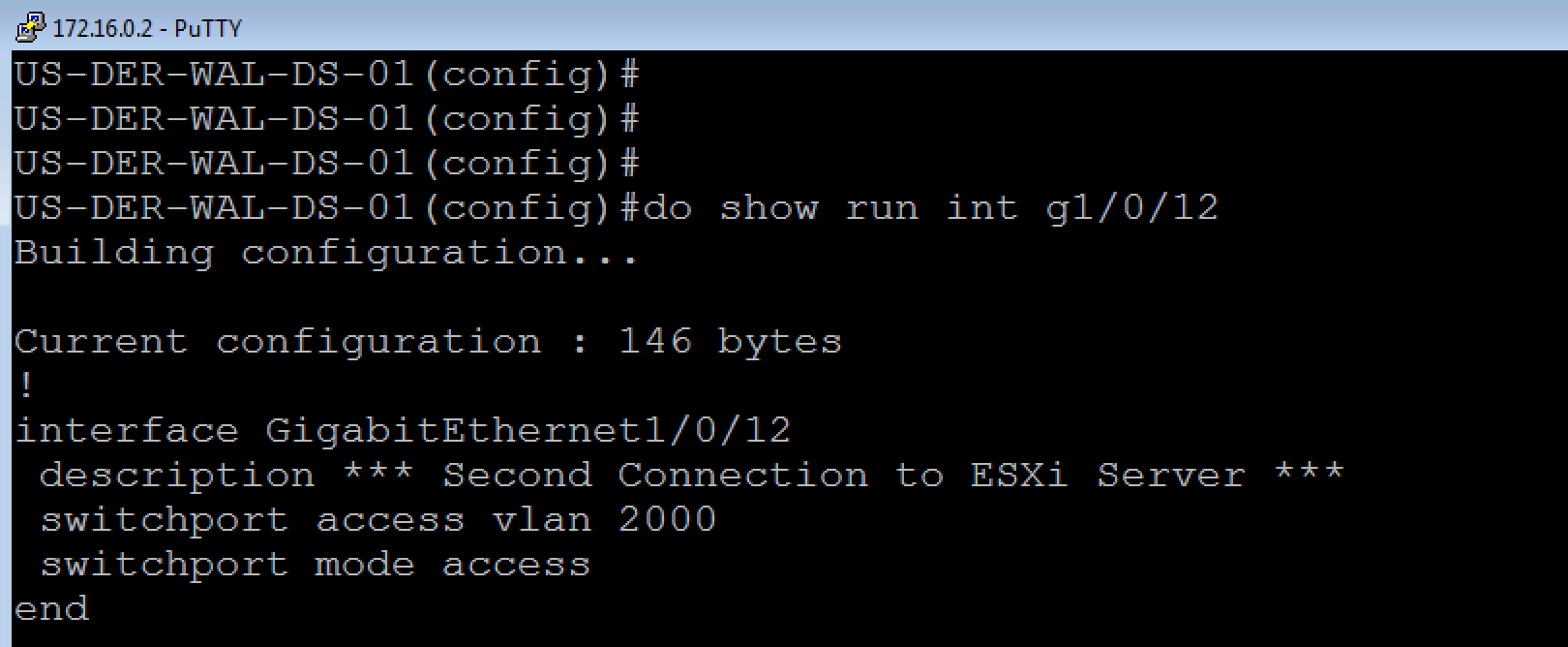
switchport access vlan 2000
switchport mode access
authentication event fail action next-method
authentication event server dead action authorize vlan 2000
authentication event server dead action authorize voice
authentication event server alive action reinitialize
authentication host-mode multi-auth
authentication open
authentication order mab dot1x
authentication priority dot1x mab
authentication port-control auto
authentication periodic
authentication timer reauthenticate server
authentication timer inactivity server
authentication violation restrict
mab
dot1x pae authenticator
dot1x timeout tx-period 10
spanning-tree portfast
Above is the ISE Specific switchport configuration that we apply to enable ISE Authentication on a port. When we have applied this configuration, sometimes with a few modifications, we state that we have “ISED” the port/device.
Here is how this looks on our lab switch.
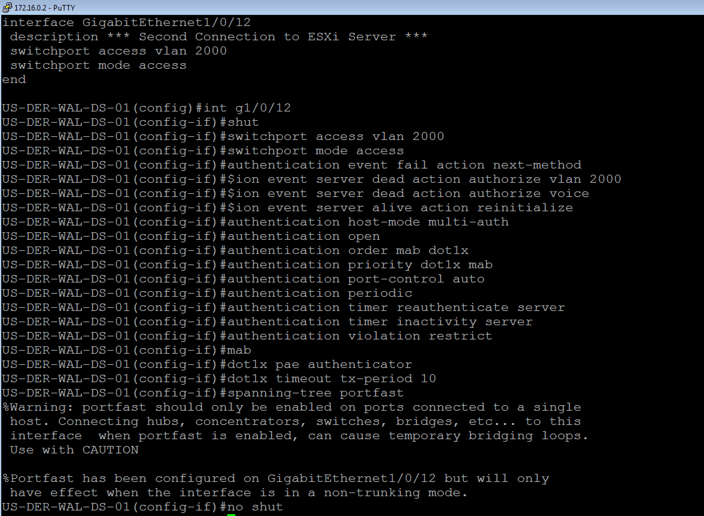
NOTE: In our Lab we are only really applying these configurations to one port, but in a real world deployment you would be applying these to a ton of ports. I highly recommend the use of the “default interface” and “interface range” commands to help you speed up this process, just make sure you check to see if there is any POE (show power inline) or CDP (show cdp n) device that may not have been identified before hand or you might just break a device’s connectivity when you ISE the port.
Here is a sample Default Interface and Interface range configuration and how it looks.
default interface range g1/0/1-48
default interface range g2/0/1-48
interface range g1/0/1-48
shut
! insert port config here
no shut
interface range g2/0/1-48
shut
! insert port config here
no shut
4. The ISE Cluster Configuration for our Network Access Device
Now that we have the switch configured for ISE, we need to configure the ISE Cluster for the switch. Launch a browser, browse to your ISE Cluster, and log into it. As usual my browser of choice is Chrome.
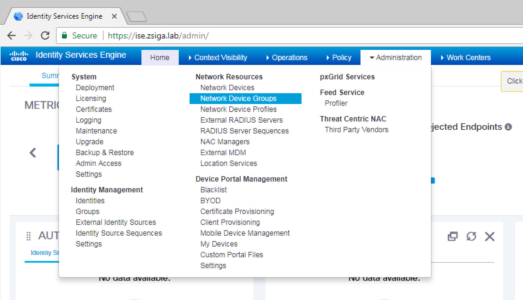
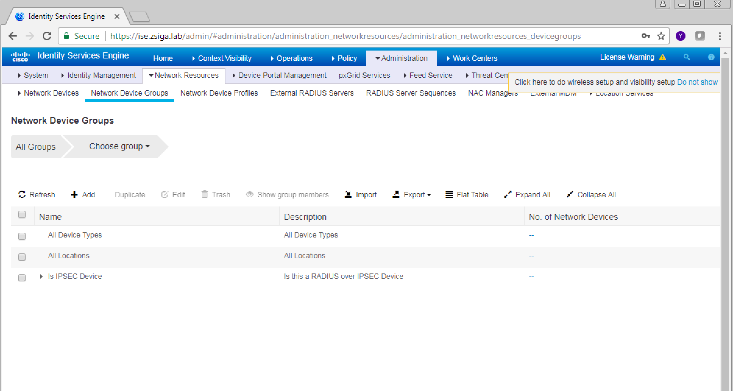
Once logged into your ISE Cluster, we are going to create a Network Device Group called Switches. To do this travel too Administration -> Network Resources -> Network Device Groups. As usual, here is a screenshot showing you this menu path as well.
On this next screen, the Network Device groups window, click the Add button to create a new group.
NOTE: You can really do a lot with different Network Device Groups. I traditionally will try to make an organization plan before I start which will reflect my specific use cases I am looking to implement. For example, you can create a number of Device Groups based on device type and then you can create a number of Device Groups based on the actual location of the device.
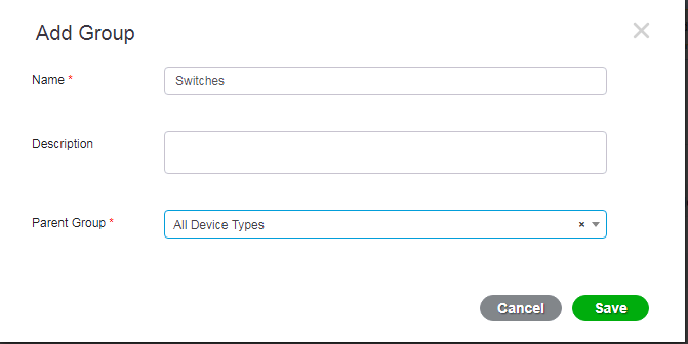
In this next little popup window, we are going to name our Group “Switches” and select All Device Types as the Parent Group. This allows us to create nested groups that we can use later on if we want. Once you have your information filled out appropriately, select Save.
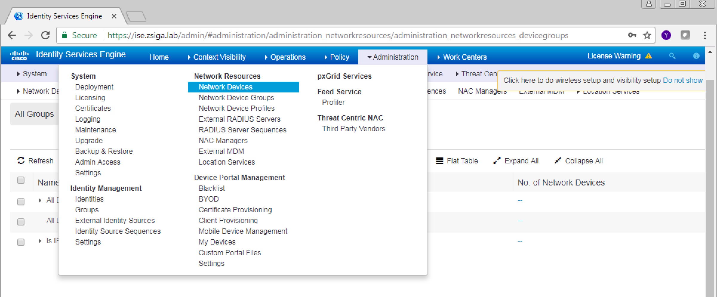
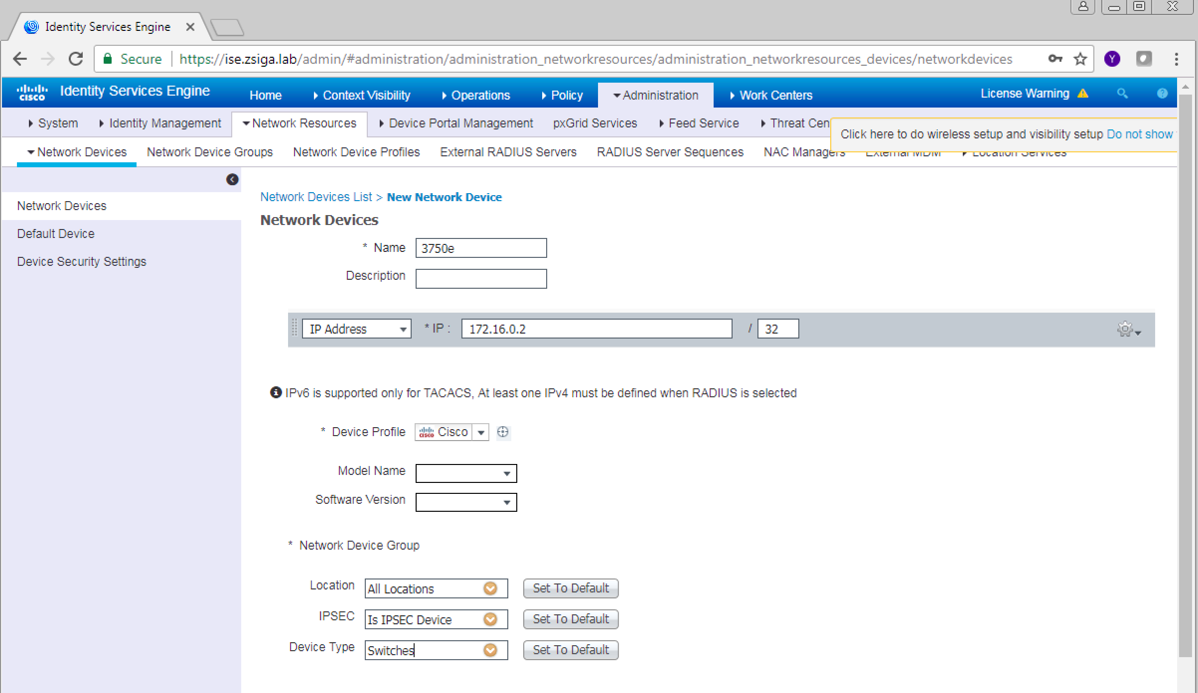
Now lets actually add our Network Access Device. Navigate to Administration -> Network Resources -> Network Devices.
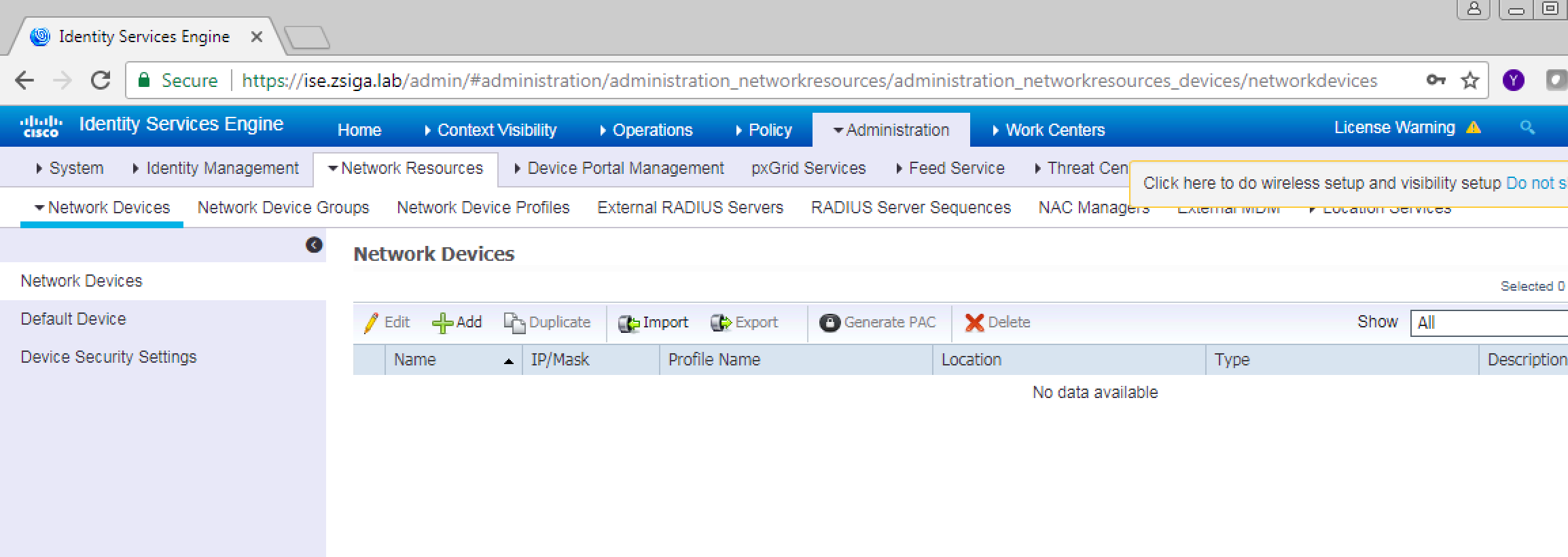
On the next window, find the Add button on the right pane and click it.
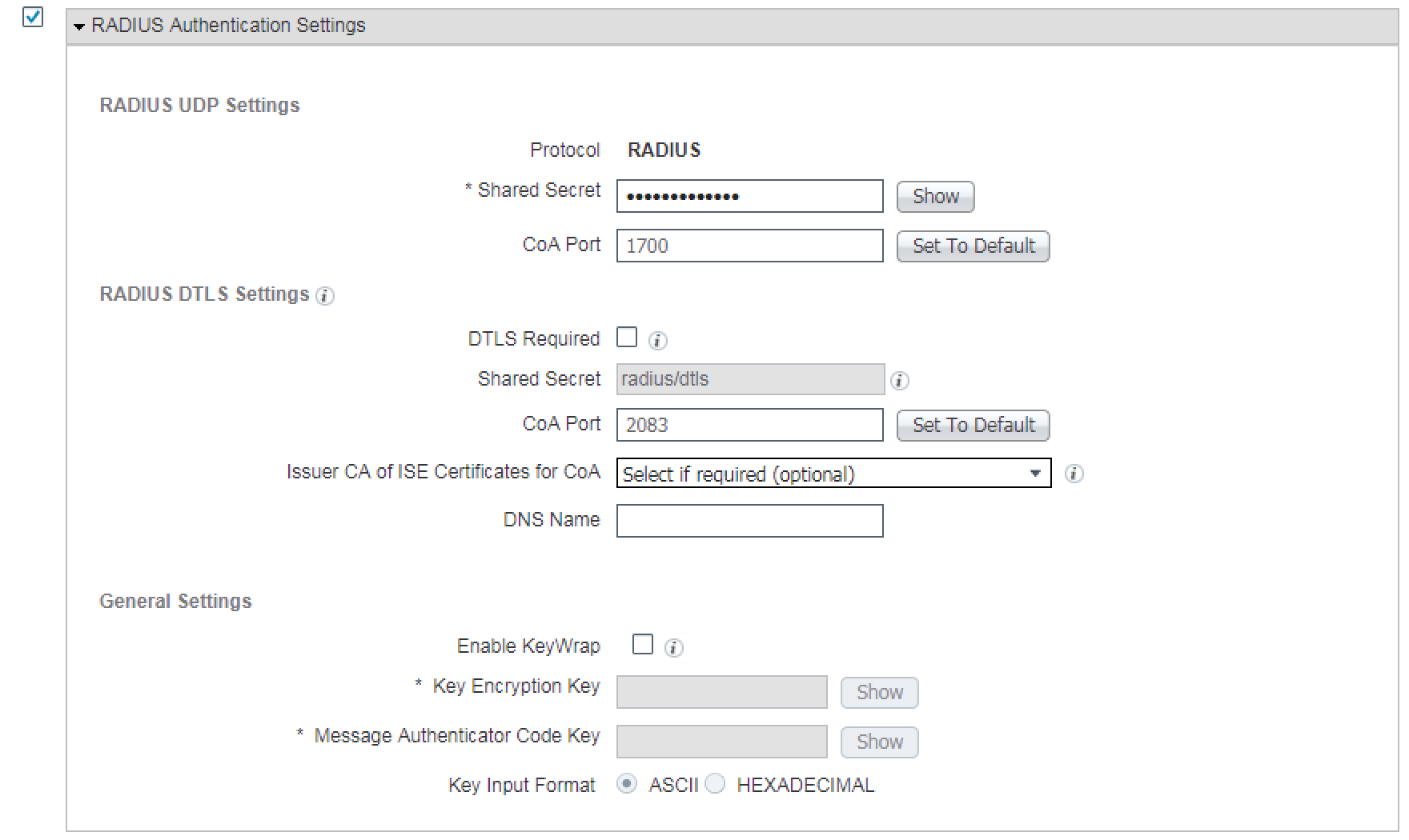
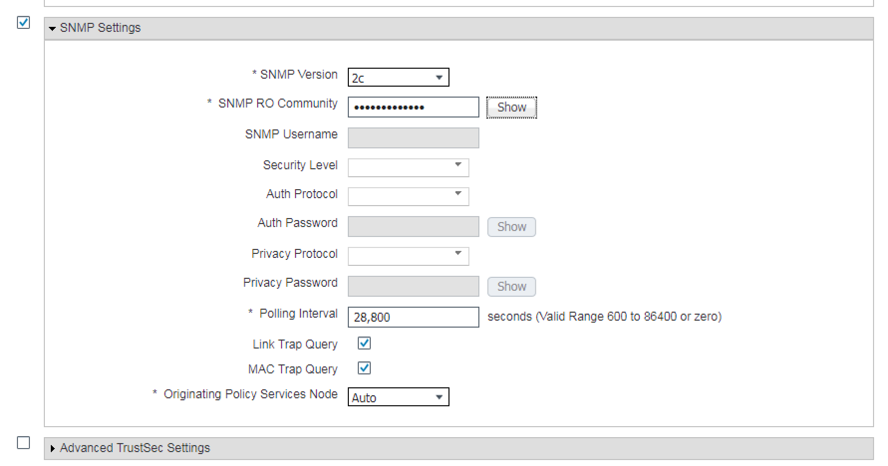
On this next window is where you are going to enter all of your switch’s specific information from IP Address, name, radius settings, snmp settings, and any other functionality you want to run between ISE and your switch. In our lab we are going to run Radius and SNMP so you will see our we configured it below.
Name, IP Address, and Device Group Selection for our Switch.
The Radius settings for our switch.
And finally, the SNMP settings for our switch.
Once you have filled in all of the settings for your device, click the save button.
You should now see a list of the devices you have configured, in our screenshot we only have the one 3750e configured currently.
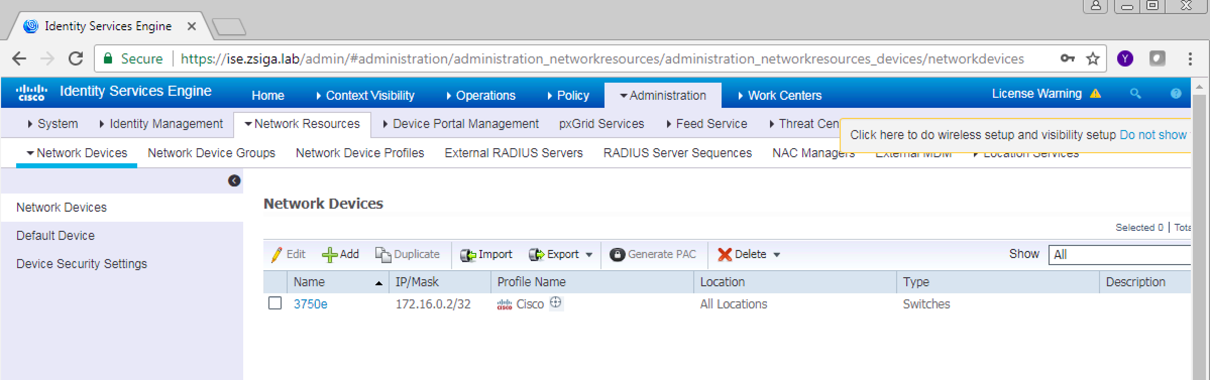
Thats it, we now have our 3750e switch and ISE configured to work together.
Related Resources:
How To: Universal IOS Switch Config for ISE
Ask questions and give feedback
- You can leave a comment on the blog!
- You can leave a voicemail at (617) 913-4103
- You can email us at Feedback@zigbits.tech
Engage with Zigbits further:
- Subscribe to the podcast on an iPhone or on an Android
- Follow Zigbits on Twitter!
- Follow Zigbits on LinkedIn!
- Follow Zigbits on Facebook!
Engage with me further:
Transparency:
This post may contain affiliate links to products or services were I may receive a level of compensation from your actions by following those links. This is seamless to you and does not add any additional cost to the products or services in question. In addition, I do not let any affiliate relationship cloud my judgement or my recommendation of a product or service. My recommendations will always be above reproach. This is my commitment to you Ziglets!
I have ISE 2.3 and have been trying to get a 3560 and a 2960S Cisco switches to communicate via SNMP v3 but no success. I’m starting to think there is an issue. ANy thoughts on this?
Hey Harry, thanks for the comment. I have been able to get SNMP v3 to work in ISE 2.3 on a number of devices. Do you have any other devices that SNMPv3 is working on? I would probably recommend you review the Cisco ISE 2.3 Compatibility Matrix to make sure you are running supported code on your 3560 and 2960S. If you are then I would rule it down to a possible configuration issue or a Bug. Let us know how it goes, the information could be helpful to others.