
Hey Ziglets, today we are continuing with our Cisco ISE 2.3 Blog Series by walking through deploying a Cisco Virtual Wireless LAN Controller (vWLC) in our Lab. We cannot do any of our Wireless 802.1X or Guest flows without out a Wireless setup now can we?!?! Its ISE ISE Baby time!! Lets get it done!
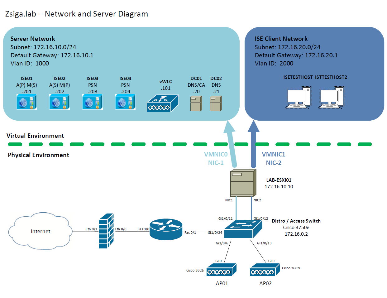
Network and Server Diagram:
Here is our reference diagram that we will be using throughout this blog series.
Related Posts:
If you haven’t seen these posts yet, you should check them out
- ZBISE01 – Basic Cisco ISE 2.3 VM Installation
- ZBISE02 – Building a Cisco ISE 2.3 Distributed Cluster
- ZBISE03 – Overview of our Cisco ISE 2.3 Use Cases for the ZBISE Blog Series
- ZBISE04 – Cisco ISE 2.3 Adding the ISE Cluster to Active Directory
The Steps!!
1. Download the Cisco Virtual Wireless LAN Controller (vWLC) OVA for your specific deployment
What version of virtual Wireless LAN Controller you deploy will depend on your design and time. Cisco updates the virtual Wireless LAN Controller versions pretty regularly so you may have a newer version of virtual Wireless LAN Controller than what I am using in this lab series. For our deployment I am going to use virtual Wireless LAN Controller version 8.0.140.
2. Deploy the Cisco Virtual Wireless LAN Controller (vWLC) OVA
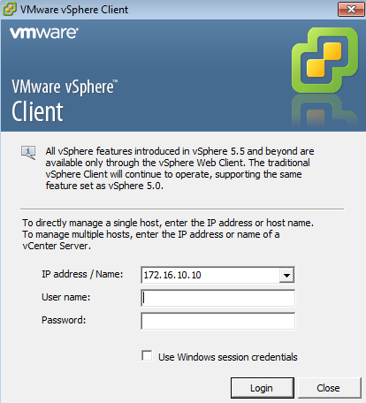
Lets launch our VMWare Client, yes I am still using an older version for those of you that are running 6.5. I’ve never been a fan of the VMWare HTML Client and prefer the desktop client.
Once the VMware Client has been launched, enter the appropriate User name and password combination for your Virtual Environment and then click Login.
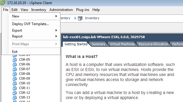
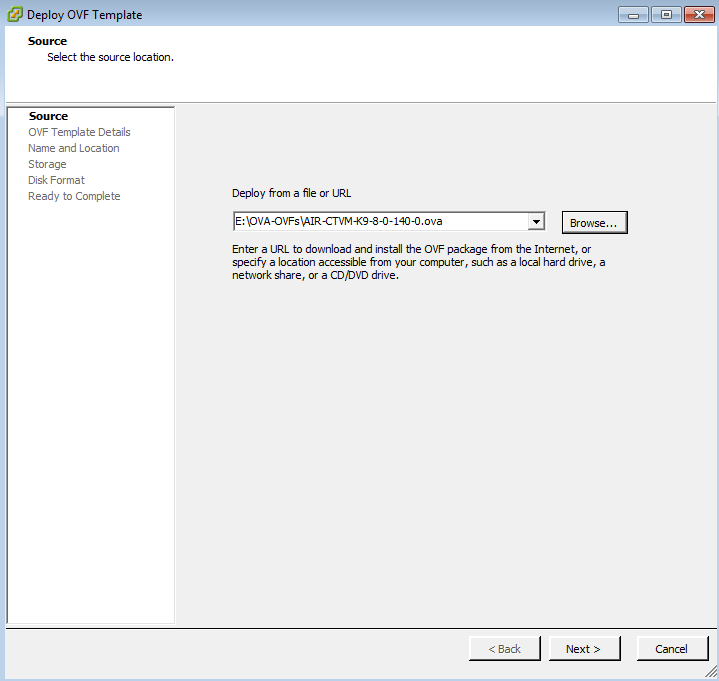
Now that you are logged into your VMware environment, select File -> Deploy OVF Template… to start the OVF/OVA Deployment Wizard.
NOTE: Depending on the Version of VMWare you might have a different option and it might be in a different location.
In the popup window, go ahead and Browse to your downloaded vWLC version, you will see in the screenshot below that the file I have is called “AIR-CTVM-K9-8-0-140-0.ova”.
Once you have the correct OVA file selected, click Next.
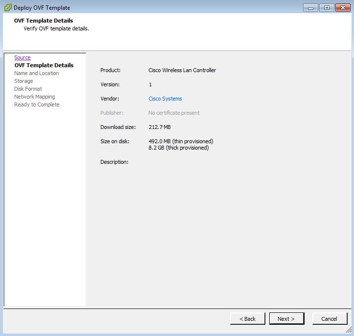
The next window shows the OVF / OVA Template Details. You will see the Vendor name that created the Template along with a number of the other details like Download size and Size on disk. Click Next to continue
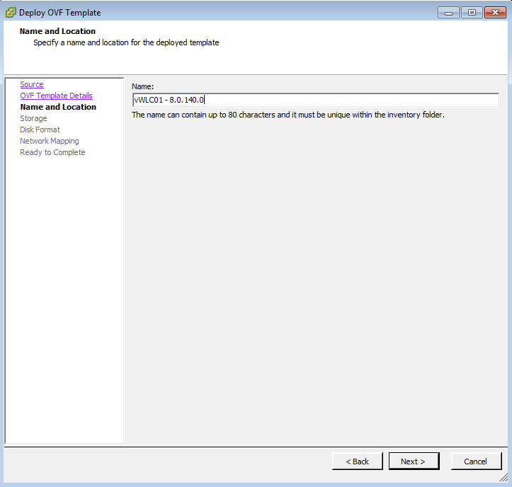
On this screen is where we can give our virtual Wireless LAN Controller a name. I’m naming mine vWLC01 – 8.0.140.0 because I usually have a few running at any given time and I like to know what version is which quickly.
When you are satisfied with your name of the VM, click Next.
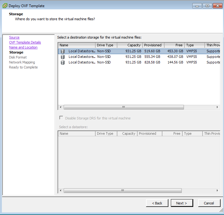
Now we get to select which Storage location to utilize for this VM. Select the location that best works for you in your design and deployment. For this VM I selected my Local Datastore 1.
Click Next when your selection is completed.
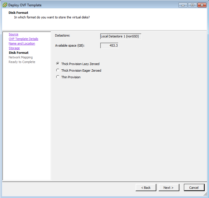
On the next screen, we get to select how we want our Disk Format to be in VMware. We can select, Thick Provision Lazy Zeroed, Thick Provision Eager Zeroed, or Thin Provision. Select the value that works for your environment. In my lab, I am using Thick Provision Lazy Zeroed.
Click Next when done.
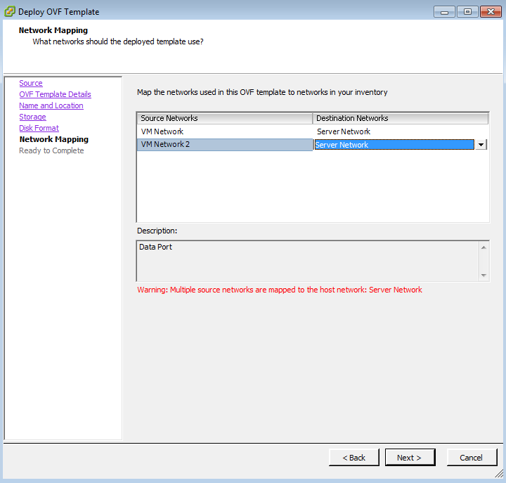
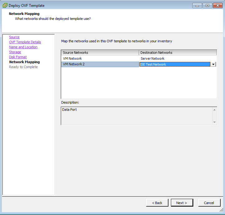
The next window is the Network Mapping window. For a virtual Wireless LAN Controller there are two NICs included in the OVF / OVA template. One is the Virtual Controller Service Port and the other one is the Data Port. It is best to have these NICs on different vSwitches in your Virtual environment. During the build out, I put one NIC on my Server Network and the other NIC on my ISE Test Network. These are different physical ports on my ESXi host that connect to our Lab switch.
NOTE. After building out our vWLC, I changed the vSwitches each NIC was connecting too. I wanted to make sure the Virtual Controller Service Port is connected to my CSR Backup Network for now (might change it later) and the Data Port is connected to my Server Network.
Once you have configured your network Mapping click next.
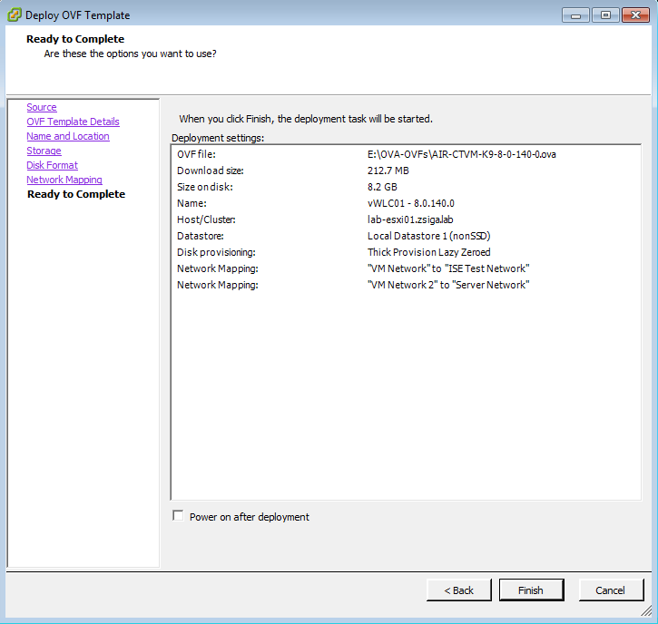
The next screen is going to be a review screen of all of the settings you have chosen up to this point. Leave the “Power on after deployment” checkbox uncheck as we want to add a virtual serial port so we can actually manage the VM once its deployed.
When you are done reviewing the settings chosen, select Finish.
While the vWLC VM is being deployed to VMware, you will see a progress bar just like the one below!
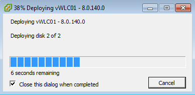
Once this bar is completed, you have deployed your Cisco Virtual Wireless LAN Controller to your VMware environment…Step 2 Done! Achievement earned! 🙂
3. Add a virtual console (serial) port to your Cisco Virtual Wireless LAN Controller (vWLC) in VMware
Congrats, you have just deployed your virtual Wireless LAN Controller into your Virtual Environment…but its not running yet. Before we start our newly born virtual Wireless LAN Controller, lets add a virtual console port so we can actually get into the vWLC Setup.
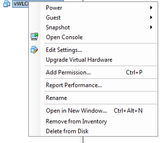
Back in VMware lets right click our vWLC and select Edit Settings…
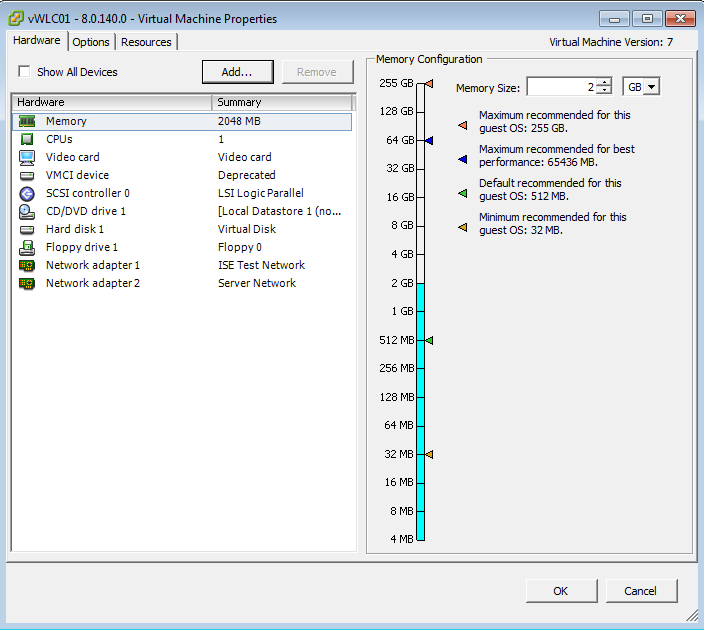
On the next window, lets click the Add… button near the top of the window. This will allow us to add virtual, and physical via pass through, hardware to our VM.
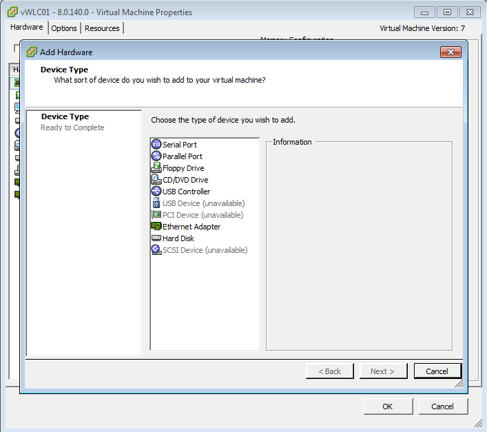
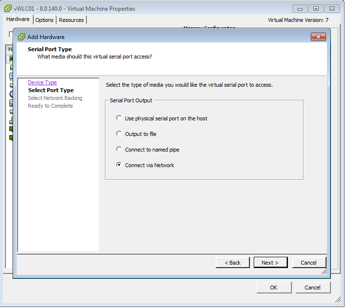
On the following screen, you will see a list of hardware options. We are going to select “Serial Port” and click Next.
Select the option “Connect via Network” and click Next.
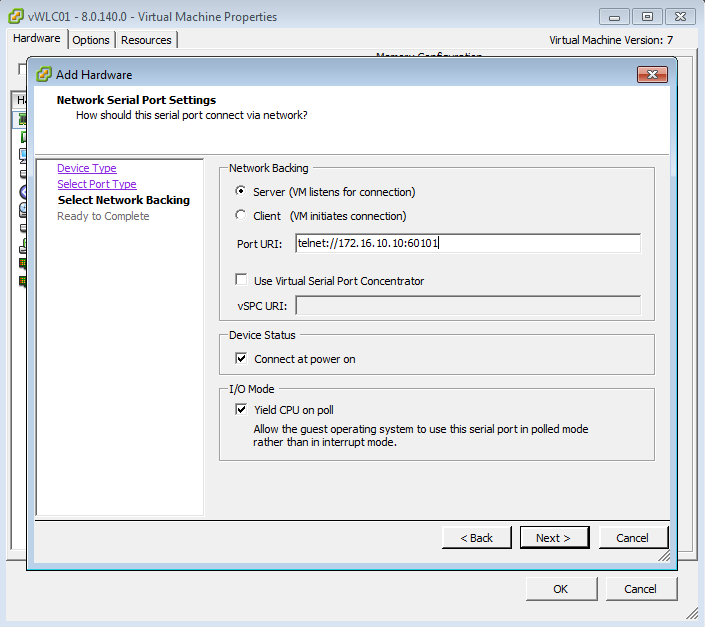
On the next screen, we have a few items that we will want to select and fill out.
Under Network Backing, select the Server option.
In the Port URI text field, I’m going to enter the following: “telnet://172.16.10.10:60101”.
The IP address 172.16.10.10 is our ESXi host and the port number 60101 is what we are configuring here for our vWLC.
I use Virtual Serial ports for a lot of VMs, so I usually will follow a port naming standard. What I am currently using in my lab is the following standard, 60YYY where YYY is the last octet of the VM’s IP address. In this case, our vWLC is going to have the IP Address of 172.16.10.101, so our port number is going to be 60101.
NOTE: Depending on your VMware environment you may need to enable a service or allow this access through a firewall.
So why are we doing this??? We are doing this because these settings are going to allow us to telnet to the VM’s console port which will allow is to configure our vWLC!! 🙂
When you have these settings configured, click Next.
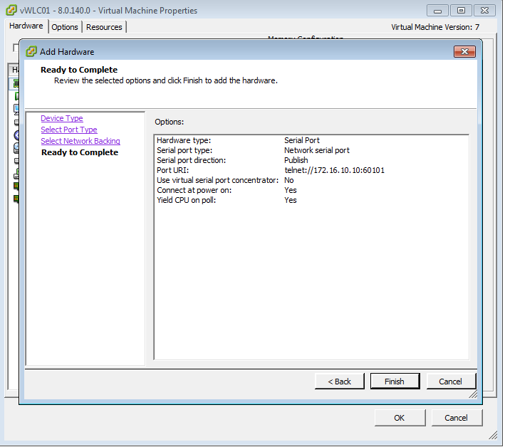
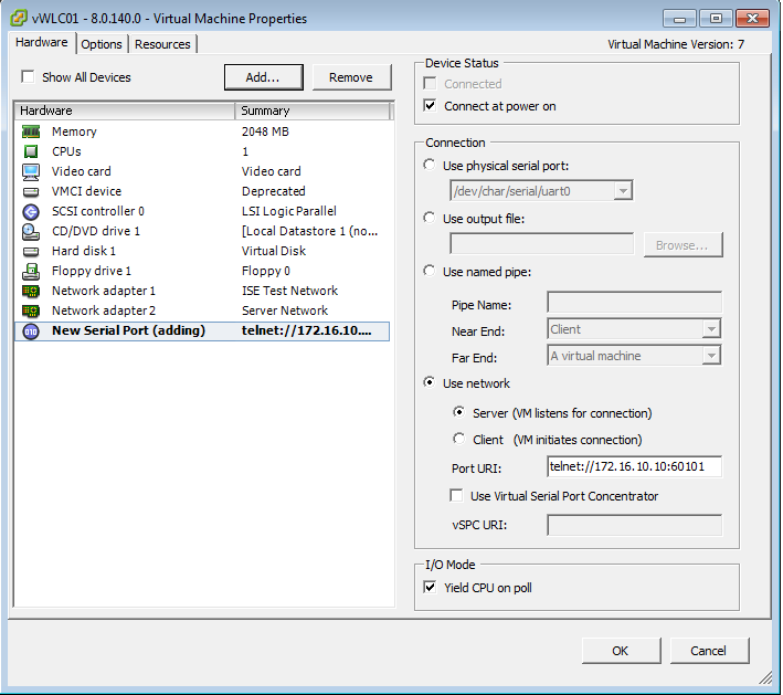
The next window gives you a review of the settings you have selected. If these look good to you, click Finish and then Ok on the last window.
We are almost there….just a little bit further now!!!!
4. Basic configuration of our Virtual Wireless LAN Controller
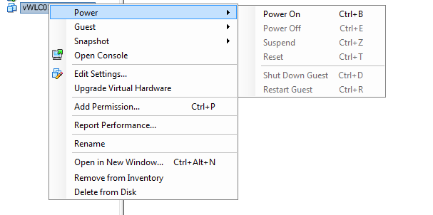
Now that we have deployed our virtual Wireless LAN Controller and configured a Virtual serial port, lets turn on our virtual Wireless LAN Controller! Right click on our VM, select Power -> Power On to turn it on!
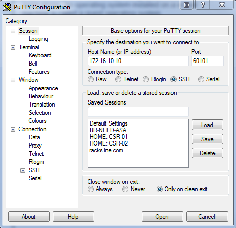
Now that our vWLC is powering up, lets connect to that Virtual Console / Serial port we created in section 3. Launch your favorite telnet client of choice, in my case its Putty.
Put in your ESXi IP Address and the corresponding Port you provided for your vWLC. In this lab environment, our ESXi host has an IP address of 172.16.10.10 and the port we assigned our vWLC is 60101.
NOTE: Make sure to select Telnet, unlike my screenshot below where I selected SSH.
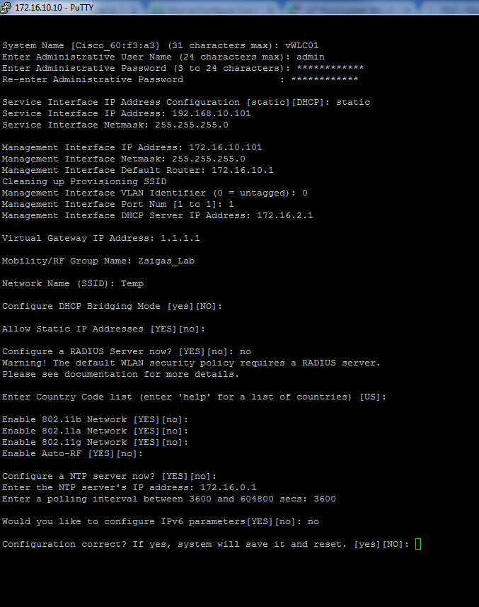
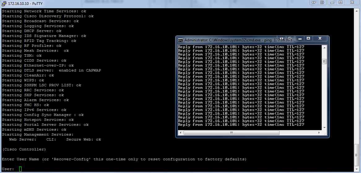
Once your telnet session is connected, you will get your vWLC command prompt. Here the setup script / wizard will most likely be asking for a hostname, as its the first question to answer.
You will need the following information for this script: Hostname, Administrator User name and Password, Service Interface IP Address and Subnet mask, Management Interface IP Address, Subnet Mask, and Default Router (Gateway), and a number of other settings. You can check out what we did for our lab vWLC in the below screenshot.
At the end of the script, you will have a validation question… Is your “Configuration correct?” If not type NO to restart the wizard / script, if yes type yes to apply the configuration, start the installation, and reboot the vWLC.
When you enter yes, the vWLC will reboot. As I like to do in other installments of this blog series, I want to verify network connectivity. Launch your favorite command window and start pinging your vWLC, in our case it will be 172.16.10.101 as shown in the below screenshot.
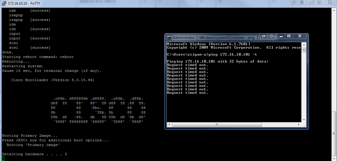
The vWLC installation process doesn’t take long and you can see it take place in your telnet session. While the installation is working, you should start to see that you can ping your vWLC as long as everything was configured correctly.
Below is a good screenshot of what you should be expecting to see.
Once the installation is completed, lets start verify management capabilities (SSH and HTTPS).
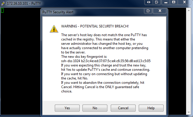
Lets ssh to our vWLC, in our case 172.16.10.101. If you get a Security Alert Screen, select the appropriate option that is correct for your environment.
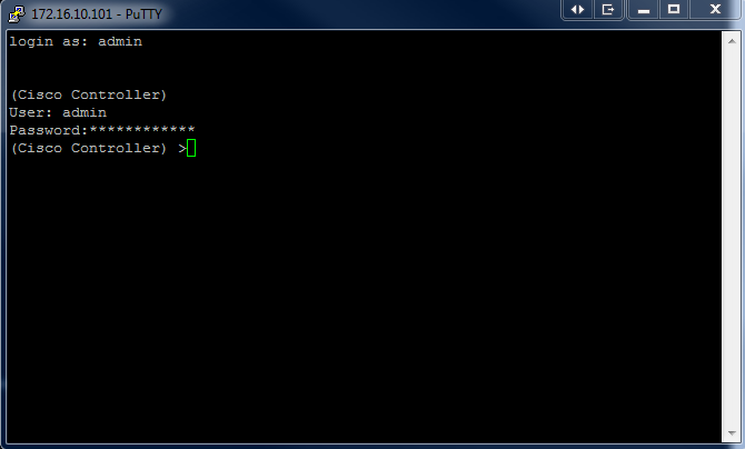
Below is a screenshot showing our Security Alert popup. Once you get past this popup, you should be at a login prompt. Enter the username and password credentials you provided in the vWLC Setup wizard to log into the vWLC. Once you make it to the “(Cisco Controller) >” prompt you are good to go with SSH access.
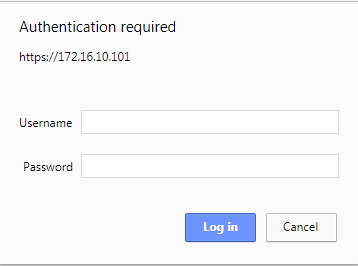
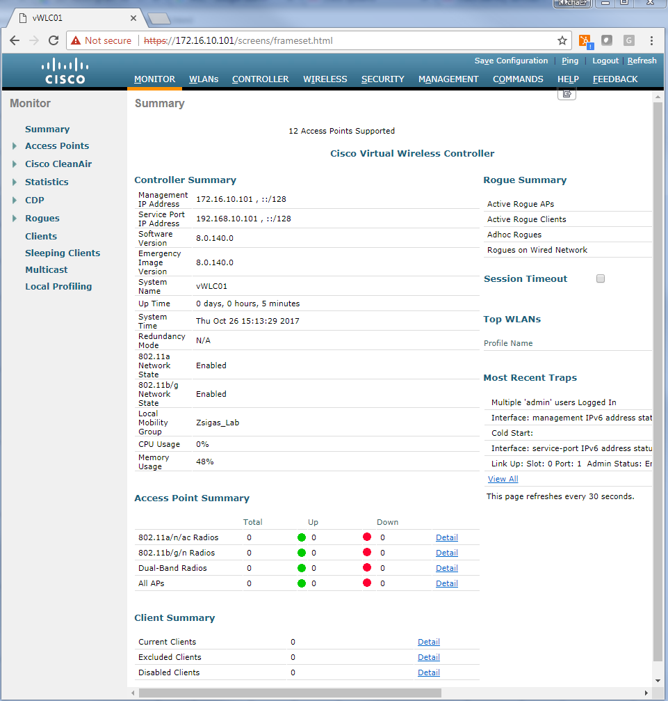
Finally lets verify our https access. Launch your favorite internet browser, in our case its going to be Chrome. Browse to your vWLC, in our case https://172.16.10.101. You may receive a Certificate warning, bypass it for now to get into your vWLC.
When the vWLC screen loads, Select the Login button and when prompted, enter the same credentials you supplied in the vWLC Setup wizard.
Once logged into your vWLC, you will see a screen like the below screenshot.
That’s it for this Zigbit! You now have a Basic Cisco Virtual Wireless LAN Controller built and running, ready to receive our ISE 2.3 configurations!!
Related Resources:
Ask questions and give feedback
- You can leave a comment on the blog!
- You can leave a voicemail at (617) 913-4103
- You can email us at Feedback@zigbits.tech
Engage with Zigbits further:
- Subscribe to the podcast on an iPhone or on an Android
- Follow Zigbits on Twitter!
- Follow Zigbits on LinkedIn!
- Follow Zigbits on Facebook!
Engage with me further:
Transparency:
This post may contain affiliate links to products or services were I may receive a level of compensation from your actions by following those links. This is seamless to you and does not add any additional cost to the products or services in question. In addition, I do not let any affiliate relationship cloud my judgement or my recommendation of a product or service. My recommendations will always be above reproach. This is my commitment to you Ziglets!